 SpanDraft
First calculation: a beam with a centered point load
This example walks through the complete SpanDraft workflow using a simply supported beam with a centered point force.
1. Define the project
A new beam project first requires a calculation title, beam length, material, and cross-section. Created by, Project, and Reference are optional. A suggested value for Created by can be changed or removed completely.
For this example, use:
- calculation title Beam with centered point load;
- beam length
L = 2 m; - material S235JR;
- rectangular cross-section 40 × 80 mm, with width
b = 40 mmand heighth = 80 mm; - bending axis y-y.
The bending axis is part of the model. It determines which cross-section properties are used for flexural rigidity and bending stress. For a rectangle, y-y is the axis parallel to its width.
2. Define the supports
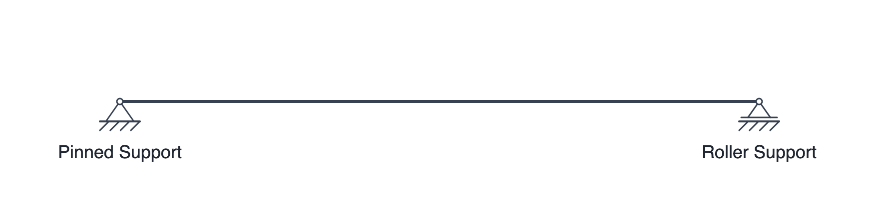
The next step is to define how the beam is restrained. In this example, place a Pinned Support at the left end and a Roller Support at the right end.
This combination prevents rigid-body motion while allowing rotation at both supports.
3. Add the load
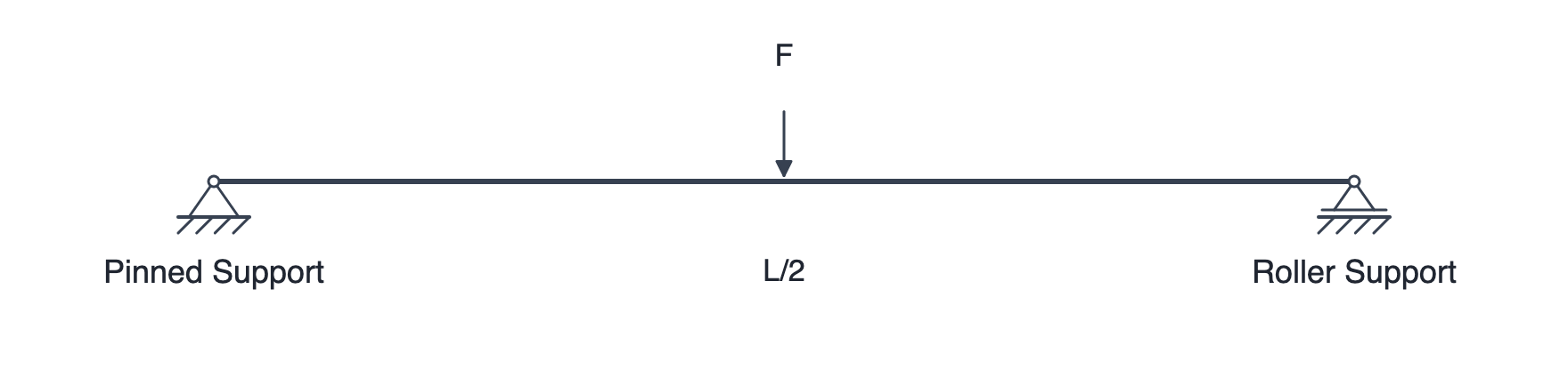
A 1 kN point force acts downward at the center of the beam.
SpanDraft defines the positive w direction as upward. The force is therefore entered as F = −1 kN at x = L/2 = 1 m.
4. Calculate automatically and review the results
As soon as the supports and loads form a solvable model, SpanDraft updates the results automatically after confirmed changes.
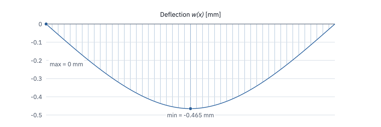
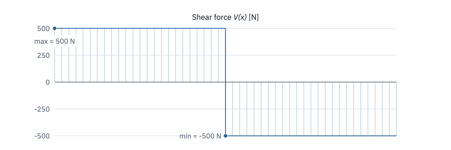
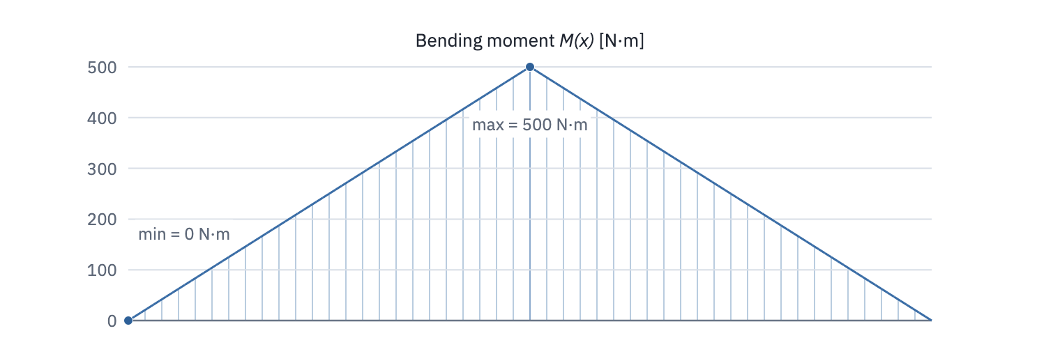
The diagrams show deflection w(x), shear force V(x), and bending moment M(x).
SpanDraft also provides the support reactions, maximum deflection, governing moment, maximum elastic bending stress, and safety factor.
For this example:
- the magnitude of the deflection is greatest at the center;
- the shear-force diagram has a jump at the point force;
- the maximum bending moment occurs at the center.
For more details, see Result diagrams and support reactions, Bending stress and safety factor, and What SpanDraft calculates – and what it does not.
5. Save the project
The completed model can be saved as a .spandraft project and opened again later. The inputs are stored in the project file; the results are recalculated when the project is opened.