 SpanDraft
Technical documentation
The technical documentation describes how SpanDraft calculates and why it calculates that way. It is written for anyone who wants to follow a result, check it, or use it in their own engineering checks: engineers, reviewers, students and instructors. How to operate the application is explained in the help.
What SpanDraft calculates
SpanDraft calculates a single straight beam with constant material and constant cross-section in one selected bending plane. It can rest on pinned supports, roller supports and fixed supports, and it carries point forces, point moments, constant distributed loads over part or all of its length, and its self-weight. SpanDraft calculates statically determinate and statically indeterminate beam systems, including continuous beams on several supports, provided the support arrangement is stable.
The results are the curves of deflection , rotation , shear force and bending moment over the full length, their extreme values with location, and the support reactions. From these, SpanDraft determines the maximum elastic bending stress and the safety factor with respect to the strength value of the material.
Among other things, SpanDraft does not calculate biaxial bending, axial forces from loads, elastic supports, hinges, variable stiffness, shear deformation, or stability cases such as buckling. The safety factor does not replace a verification according to a standard. The limits are explained in the chapters Calculation model and assumptions and Safety factor and assessment limits.
Where to start
Not every question needs every chapter. For common concerns, a short path is enough:
- Follow a result: Calculation model and assumptions, then Loads, supports and internal forces and moments and Continuous results and extreme values.
- Put stress and safety factor in context: Bending stress and extreme fibers, then Safety factor and assessment limits.
- Check cross-section properties: Cross-section geometry and properties, then Parametric cross-section shapes.
- Judge the calculation itself: Solver verification, then Numerical solution and accuracy.
Sign convention and notation
All chapters use the same sign convention. The coordinate starts at the left end of the beam and points to the right. Deflection, forces and distributed loads are positive upward, rotations and moments counterclockwise. A positive bending moment is sagging: it pulls the bottom side.
The input and display of coordinates and units are explained in the help.
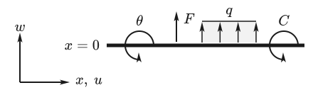
Where the convention differs from common textbooks, the chapter says so at that point. Symbols follow ISO 80000-2: quantities are set in italics, units and descriptive subscripts upright.
Structure of the documentation
The chapters build on one another but can also be read individually. Each begins with a summary, derives its statements in a traceable way and names its sources. Where the general theory and the implementation in SpanDraft differ, both are shown side by side.
Mechanical fundamentals
The mechanical model on which all further chapters build.
- Calculation model and assumptions: beam model, linearity assumptions and scope of validity.
- Euler–Bernoulli beam theory: from the distributed load via shear force, moment and curvature to the deflection.
- Loads, supports and internal forces and moments: signs, load types, support conditions and jump locations.
Materials
Which properties a material provides and where the built-in values come from.
- Material properties: Young’s modulus, density, Poisson’s ratio, yield strength and 0.2 % proof strength.
- Material library and reference values: storage in library and project, and the reference values of the built-in materials.
Cross-sections
How the properties of a cross-section follow from its outline.
- Cross-section geometry and properties: area, centroid, second moments of area, principal axes and section moduli.
- Parametric cross-section shapes: outlines from input dimensions and the bending axes of each shape.
Calculation methods and solver
How the beam problem is solved without dividing the beam into elements.
- State variables and transfer: closed-form integration of the beam equation and loads as analytical load integrals.
- Stations and equation system: supports as stations, the small equation system and the detection of unstable support arrangements.
- Continuous results and extreme values: analytical curves, one-sided values at jump locations and extreme values without a grid.
- Numerical solution and accuracy: solving in floating-point numbers and the error check that decides whether a result is output.
Engineering evaluation
What follows from the internal forces and moments for the assessment of a component, and where that statement ends.
- Bending stress and extreme fibers: maximum elastic bending stress and governing extreme fiber.
- Safety factor and assessment limits: what the safety factor states and which verifications it does not replace.
Verification
What shows that the solver calculates correctly.
- Solver verification: test methods, acceptance result and limits of the statement.
- Analytical reference cases: nine cases with a stored, independently derived closed-form reference solution in direct comparison.
- External reference solvers: comparison with IndeterminateBeam and PyCBA.
- Physical and metamorphic checks: equilibrium, jumps, scaling and superposition without a reference solution.
Status of the documentation
The documentation describes the current solver. Its acceptance of November 11, 2026 passed all 18 cases of the validation catalog; the scope and limits of this evidence are given in the chapter Solver verification. New chapters appear first in German, and the English translation follows.
For developers, the solver documentation in the source repository complements the technical documentation as an implementation and source reference.