 SpanDraft
Loads, supports and internal forces and moments
A beam problem is not determined by its stiffness alone. External loads and support conditions are equally decisive. From them arise support reactions and internal forces and moments.1,2
A fixed sign convention is necessary for an unambiguous interpretation. Textbooks and calculation programs use different conventions, especially for shear force, bending moment and distributed load. The following definitions are binding for SpanDraft.
Coordinates and signs
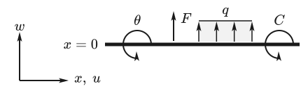
The beam axis begins at the left end of the beam at and runs to the right. Positive axial displacements point to the right, positive transverse displacements upward. Positive rotations and external moments act counterclockwise.
Positive point forces and positive distributed loads act upward.
For the internal forces and moments, the following applies:
- for tension,
- for a positive, sagging bending moment,
- according to the definition .
Within a connected beam section, therefore holds at the same time.
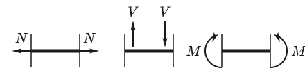
Other sources may, for example, define a downward distributed load as positive or use a different sign for the shear force.1,3,4 Such conventions are possible as well, but must not be mixed with the SpanDraft signs.
External loads, support reactions and internal forces and moments
Three kinds of mechanical quantities must be distinguished here.1,2
External loads are prescribed. They include, for example, an entered point force, a point moment or a distributed load.
Support reactions arise because supports prevent certain movements. Their magnitude is not prescribed but results from the calculation.
Internal forces and moments describe the internal forces and moments in the beam. They become visible when the beam is cut at a location in thought.1,2
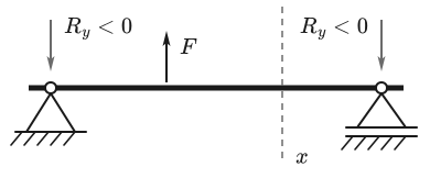
The imagined cut separates the beam into two parts. In the free-body cut, the effects of the removed part of the beam at the cut face are replaced by internal forces and moments. For the planar beam model, these are the axial force , the shear force and the bending moment .1,2
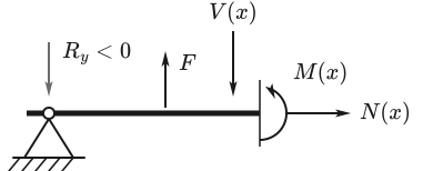
Internal forces and moments are not additionally entered loads. They result from equilibrium, support conditions and deformation of the beam.
Load types
Point force
A point force acts at a specific position of the beam. In SpanDraft, a positive force is directed upward and a negative force downward.
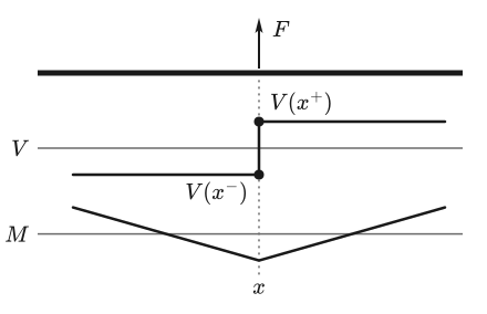
A concentrated force causes a jump in the shear force curve at its position.3,4 Without an additional point moment, the bending moment curve remains continuous; only its slope changes.
Point moment
A concentrated external moment is denoted here by so that exclusively denotes the internal bending moment .
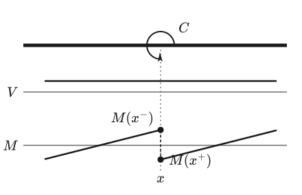
Positive external moments act counterclockwise. A point moment produces a jump in the bending moment, but not in the shear force.3,4
Distributed load
A distributed load — also called a line load — describes a force distributed over a length of the beam. Its intensity has the unit .1,2
In general beam theory, can depend on location.3 SpanDraft uses constant distributed loads between a start position and an end position.
Several distributed loads may overlap. Within a common region, their intensities are added with their signs.
Self-weight
If self-weight is enabled, SpanDraft derives from it an additional constant distributed load over the entire beam length.
with the standard gravity . is the material density and the cross-sectional area. The negative sign follows from the SpanDraft convention: self-weight acts downward.
For the solver, self-weight is an ordinary constant distributed load. Only its intensity is calculated from material and cross-section.
Supports as boundary conditions
Supports prevent certain movements of the beam.1,5 In the planar SpanDraft model, every point of the beam axis has three kinematic degrees of freedom: the axial displacement , the transverse displacement and the rotation . A support defines which of them are constrained at its position. If different support types are at the same position, their constraints combine.
| Support | Symbol | |||
|---|---|---|---|---|
| Fixed support | 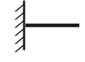 | constrained | constrained | constrained |
| Pinned support | 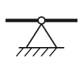 | constrained | constrained | free |
| Roller support | 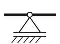 | free | constrained | free |
A constrained movement can give rise to a corresponding support reaction.1,5 A constraint on can lead to an axial reaction, a constraint on to a transverse reaction, and a constrained rotation to a reaction moment. SpanDraft outputs exactly one reaction per support position and constrained direction. Because there are no external axial loads, the axial reaction there is always zero.
A support reaction can nevertheless be zero. A degree of freedom can be constrained without the load case under consideration requiring a force or a moment there.
With several supports, all support conditions must be satisfied together with equilibrium and deformation compatibility.1,5
A support is not automatically a hinge
Especially for continuous beams, a distinction must be made between a support and an internal hinge release.1,5
In SpanDraft, a pinned support or roller support prevents the transverse displacement (). The rotation remains free there, however. It does not follow that the bending moment must also be zero at an intermediate support: can hold there.1
In SpanDraft, the beam remains continuous at the intermediate support. The adjoining beam sections share the same rotation there; there is no internal moment release.
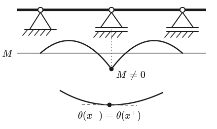
At an internal hinge, in contrast, the bending moment is zero, and the rotations of the adjoining beam sections are not coupled. They can differ from each other.1,5
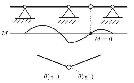
At a pinned beam end, results without an additional external end moment. There is no further beam section there through which an internal moment could be transmitted.1,6
SpanDraft currently has no internal hinge releases.
Statically determinate and statically indeterminate systems
In a statically determinate system, the unknown support reactions can be determined from the equilibrium conditions alone.1,5
In a statically indeterminate system, the equilibrium conditions are not sufficient. In addition, the deformations of the beam must be compatible with the support conditions.1,5 A typical example is a continuous beam with several vertical supports.
For a planar overall system, the equilibrium conditions
apply.
If the equilibrium conditions are not sufficient, additional compatibility conditions apply.
SpanDraft can calculate both statically determinate and statically indeterminate beam systems. How the support conditions enter the equation system is described in the chapter Stations and equation system.
Why does a different E not automatically change the support reactions?
In general statically indeterminate structures, the distribution of reactions depends on the relative stiffnesses of the regions involved. SpanDraft, however, uses a constant material and a constant cross-section over the entire beam. If is scaled by the same factor over the entire beam, the support reactions remain the same for unchanged loads, geometry and supports. Deflections and rotations, in contrast, change with the flexural rigidity. Static indeterminacy therefore means that deformation compatibility is needed for the solution. A change of Young’s modulus alone does not automatically lead to different support reactions.1
Section-by-section description of the beam
With several loads and supports, the same functional rules do not apply everywhere along the beam.
Special positions are, for example, point forces, point moments, supports, and the start and end of a distributed load. Between such locations, connected relations apply for , , , and .3,4,6
At a section boundary, the functional rule can change without the quantity under consideration jumping.
For a continuous beam without an internal hinge, and remain continuous at ordinary internal load and support locations. Internal forces and moments, in contrast, can have jumps at concentrated forces, moments or support reactions.1,3,6
The section-by-section description belongs to the mechanical model. It does not arise only through the presentation in the diagram.
Jump locations and one-sided values
At an interior location , and denote the view immediately to the left and right of the location, respectively.3,6 At a continuous location, both agree; at a jump location, or is possible. At a jump location, the value of or is therefore unambiguous only together with the side under consideration.
Jump of the shear force
If a concentrated point force or a transverse support reaction acts at , the following holds with the SpanDraft sign convention3,4:
A positive, upward force produces a positive jump in the shear force curve; a downward force produces a negative one. A kink arises in the moment curve at this location.
Jump of the bending moment
For a concentrated external moment or a reaction moment, the following holds3,4:
According to this convention, a positive external moment acting counterclockwise produces a negative jump in the bending moment. The shear force remains continuous.
Start and end of a distributed load
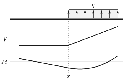
If a distributed load begins, ends or changes, this alone produces neither a jump in nor in .3,4,6 Instead, the derivative of the shear force changes:
For a constant distributed load, is linear within the loaded section. Because holds, the moment curve there is quadratic or of lower degree.3,4
SpanDraft treats the one-sided limits separately. Internal forces and moments are neither averaged nor smoothed at jump locations. For a continuous beam without an internal hinge, and , in contrast, remain continuous at load and support locations.
How SpanDraft determines the one-sided values from the adjoining pieces of the beam is explained in the chapter Continuous results and extreme values.
Relation to the result diagrams
The shear force and bending moment diagrams in SpanDraft are graphical representations of the functions and . Their shape follows directly from3,4,6:
Some typical curves can be read off directly3,4:
- A horizontal moment curve means .
- A constant shear force leads to a linear moment curve.
- A constant distributed load leads to a linear shear force curve and a quadratic moment curve.
- A jump is not a display error but can be part of the mechanical solution.
The diagrams visualize the calculated functions. The calculation of the continuous result fields and their graphical sampling are separate steps in SpanDraft.
Classification in SpanDraft
In the current beam model, SpanDraft uses transverse point forces, point moments, constant distributed loads and, optionally, self-weight as a constant distributed load derived from it. The available supports are fixed support, pinned support and roller support; several support positions, and thus statically indeterminate systems as well, are possible.
The help explains the input in the application under Supports and boundary conditions and Forces, moments and distributed loads.
Not part of the current model are, in particular, location-dependent distributed load functions, prescribed support movements, internal hinge releases and user-definable axial loads.
Together with Euler–Bernoulli beam theory, these loads and boundary conditions define the continuous mechanical problem. The group “Calculation methods and solver” then describes how SpanDraft, from this, transfers state variables, introduces boundary conditions at the stations and determines displacements, internal forces and moments, and deformations.
Sources
- Dietmar Gross; Werner Hauger; Jörg Schröder; Wolfgang A. Wall. Technische Mechanik 2 — Elastostatik. 15th edition. Springer Vieweg, Berlin, Heidelberg. 2024. DOI 10.1007/978-3-662-68423-8. Accessed .
- René Alderliesten. Basic Definitions. Introduction to Aerospace Structures and Materials, Delft University of Technology / TU Delft Open via Engineering LibreTexts. Accessed .
- René Alderliesten. Relation Among Distributed Load, Shearing Force, and Bending Moment. Introduction to Aerospace Structures and Materials, Delft University of Technology / TU Delft Open via Engineering LibreTexts. Accessed .
- Daniel W. Baker; William Haynes. Relation Between Loading, Shear and Moment. Engineering Statics: Open and Interactive via Engineering LibreTexts. Accessed .
- Felix Udoeyo. Equilibrium Structures, Support Reactions, Determinacy and Stability of Beams and Frames. Structural Analysis via Engineering LibreTexts. Accessed .
- Tomasz Wierzbicki. Governing Equations. Structural Mechanics, Massachusetts Institute of Technology / MIT OpenCourseWare via Engineering LibreTexts. Accessed .