 SpanDraft
Supports and boundary conditions
A support defines how the beam may move at one position. Rigid supports block the axial displacement u, the transverse displacement w, or the rotation θ. Springs restrain w or θ elastically: the movement is not blocked, but it produces a restoring action. Internal hinges are not supports; they release a constraint inside the beam (see Hinges).
The position x is an exact model value and may also lie inside the beam. At most one support can stand at a position; the one exception is a translational and a rotational spring together (see Translational and rotational spring at one position). The movements u, w, and θ are explained under Coordinate system and units.
| Support | Symbol | Boundary condition | Possible reactions |
|---|---|---|---|
| Fixed Support | 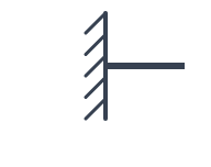 | u = 0, w = 0, θ = 0 | Rx, Ry, M |
| Pinned Support | 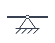 | u = 0, w = 0 | Rx, Ry |
| Roller Support | 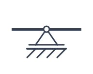 | w = 0 | Ry |
| Translational spring | 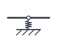 | u = 0; R = −k · w | Rx, Ry |
| Rotational spring | 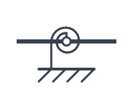 | u = 0; C = −kθ · θ | Rx, M |
R is the restoring force of the translational spring and C the restoring moment of the rotational spring. Both act on the beam; they appear as the reactions Ry and M.
Rigid supports
Fixed, Pinned, and Roller Supports are ideal: blocked movements are set to zero, and a Roller Support always blocks the transverse displacement w. Friction, clearance, and prescribed support displacements are not modeled. A movement that a support does not block stays free and produces no reaction.
Elastic supports
The translational spring and the rotational spring are separate tools in the toolbar. Every stiffness is greater than zero, and the spring is ideally linear and independent of the load. A spring support holds the beam rigidly in the axial direction (u = 0); there is no axial spring. At present Rx is always zero because SpanDraft has no external axial loads – but the boundary condition u = 0 and the reaction Rx are two different things.
Translational spring
The translational spring restrains the transverse displacement elastically. Its stiffness k (for example in N/mm) produces the restoring force R = −k · w, which is reported as the reaction Ry. The beam can still rotate freely at the support.
Rotational spring
The rotational spring restrains the rotation elastically. Its stiffness kθ (for example in kN·m/rad) produces the restoring moment C = −kθ · θ, which is reported as the reaction M. The transverse displacement stays free at the support unless you select Rigid in w.
Rigid in w blocks the transverse displacement rigidly (w = 0) and keeps the rotation elastic: a partial restraint. The reactions are then Ry as a rigid support force and M as the spring moment. The option exists for the rotational spring only. It is a mechanical property of its own and does not switch a spring on.
Translational and rotational spring at one position
A translational spring and a rotational spring are two independent supports, also at the same position. Each has its own name, position, and stiffness; you select, move, edit, and delete them one by one. If you place the second spring at the position of the first, you simply get another support with the next name. Both are calculated together; the overview shows one reaction row per position (for example A + B).
Exactly one translational and one rotational spring can share a position. SpanDraft refuses two translational springs, two rotational springs, a spring together with a rigid support, and more than two supports. Rigid in w is not available at a position with a translational spring. If you change a spring to the kind that already stands there, SpanDraft refuses it when you confirm.
You select the units of the stiffnesses in the settings.
Providing sufficient restraint
The rigid beam must not be able to move without a support holding it. For that, the axial displacement u has to be blocked at least once, and the transverse displacement together with the rotation has to be excluded – by a Fixed Support, by transverse restraint at two different positions, or by a transverse restraint combined with a rotational one. Several supports do not create internal hinges; you place hinges explicitly.
- A Fixed Support is sufficient on its own.
- A Pinned Support alone still allows rotation about its support point. A Pinned Support combined with a Roller Support at another position is sufficient.
- Two Roller Supports leave axial rigid-body motion free. SpanDraft then cannot solve the model even if no external axial load is applied.
Springs count by the direction in which they act, not by their value: a translational spring acts like a transverse restraint, a rotational spring like a rotational restraint, and every spring support blocks u. A beam resting on springs alone is therefore solvable if
- two translational springs stand at different positions,
- a translational spring and a rotational spring stand at the same or at different positions, or
- the rotational spring has Rigid in w.
A single translational spring leaves the rotation about its position free, a single rotational spring leaves the translation free, and rotational springs alone do not restrain any transverse displacement. Springs can be combined with rigid supports; here too, the movements blocked in total decide. A spring can share its position only with the spring of the other kind, never with a rigid support.
SpanDraft has no stiffness limit and does not replace a rigid support by a spring: a very stiff spring is still a spring, even if it behaves almost rigidly. For extreme stiffnesses or springs that are extremely close together, SpanDraft may reject the model as numerically not reliably solvable instead of returning a doubtful result.
Hinges
A hinge is a moment release in the beam: the bending moment is zero on both sides, and the beam may kink there. Deflection, shear force, and axial force are transmitted. A Gerber beam is the typical example. The hinge tool sits behind the supports in the toolbar; the ring on the beam axis is placed, dragged, and edited like a support.
- A hinge lies inside the beam, not at an end, and at most one hinge is allowed at a position.
- It may lie on a Pinned Support, a Roller Support, or a translational spring, at a segment boundary, under a distributed load, and at a point force. A hinge is not possible on a Fixed Support, on a support with a rotational spring (also next to a translational spring or with Rigid in w), or at a point moment. The tools refuse such a position already while you place it.
- Each hinge removes one restraint from the beam, so a beam with hinges needs correspondingly more supports: Pinned–Roller–Roller with one hinge is determinate, with two hinges it is a mechanism. SpanDraft detects mechanisms exactly and then reports that the support is insufficient or that there are too many hinges.
In the overview and in the report, the Hinge results table shows the rotation to the left θ− and to the right θ+ of the hinge and the transmitted shear force V; at a hinge over a support or with a load the shear force jumps, and both values are shown. The deflection diagram shows the kink. Choose the support type according to the actual movement constraints. For details, see What SpanDraft calculates – and what it does not.
Next: Forces, moments and distributed loads.
Technical background: Loads, supports and internal forces and moments.