 SpanDraft
Coordinate system and units
Beam coordinates
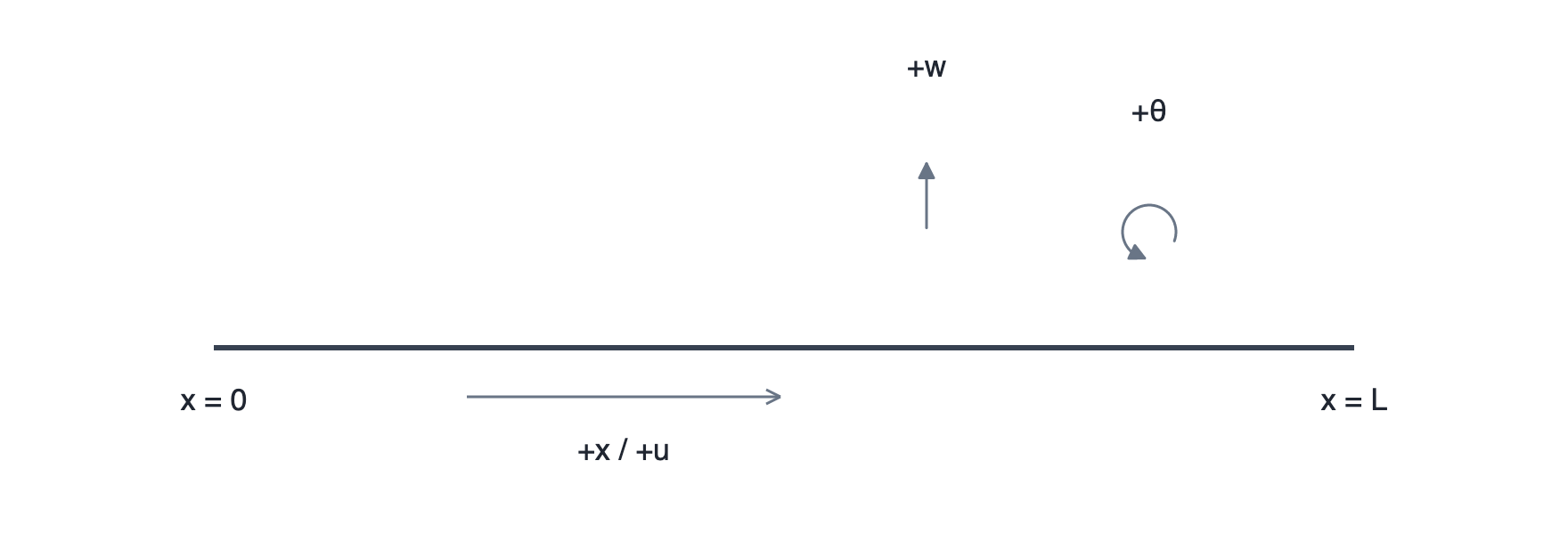
| Quantity | Positive direction |
|---|---|
x, u |
to the right |
w |
upward |
θ |
counterclockwise |
x = 0 is at the left end and x = L at the right end.
Positions are actual model coordinates and remain independent of any visual distortion used to improve readability of the schematic.
The load sign conventions and reaction sign conventions are described with the respective quantities.
The beam coordinates x/u/w/θ should not be confused with the local cross-section axes y/z or u/v; see Beam, material and cross-section.
Units
SpanDraft provides the profiles Mechanical engineering (default), Structural engineering, and US customary, as well as custom combinations.
| Quantity | Mechanical engineering | Structural engineering | US customary |
|---|---|---|---|
| Beam length / position | mm | m | ft |
| Force | N | kN | kip |
| Moment | N·m | kN·m | kip·ft |
| Section dimensions | mm | mm | in |
| Deflection | mm | mm | in |
Section area A | mm² | cm² | in² |
Second moment of area I | mm⁴ | cm⁴ | in⁴ |
Section modulus W | mm³ | cm³ | in³ |
| Distributed load | N/m | kN/m | kip/ft |
| Stress | MPa | MPa | ksi |
| Young’s modulus | GPa | GPa | ksi |
| Strength value | MPa | MPa | ksi |
| Density | kg/m³ | kg/m³ | kg/m³ |
| Rotation | rad | rad | rad |
Changing units affects presentation only. Internally, SpanDraft calculates with SI values; the mechanical model and physical results remain unchanged.
A value that is currently being edited may need to be confirmed or canceled before the units can be changed.
Number formatting
All displayed numbers – given values, library values and results – follow the same rule. Rounding sets the level n from 1 (coarse) to 5 (fine) (default: 3). Each value is rounded on its own, in the selected unit:
- Digits before the decimal separator are never lost:
1234.5 Nis displayed as1 235 N, and12.375 mmas12.4 mm. - Halves are rounded away from zero, and trailing zeros are omitted (
12.0 mmbecomes12 mm,999.6 Nbecomes1 000 N). - A safety factor is never rounded up:
0.9995is displayed as0.999. Exactly zero is displayed as0, and an infinite safety factor as∞.
Given values – lengths, positions, loads, cross-section dimensions and material and section properties – are marked with ≈ when the display differs from the entered value: 800 mm stays 800 mm, while 800.000004 mm is displayed as ≈ 800 mm. In labels, ≈ replaces the equals sign, for example F1 ≈ 800 mm. Exact values and exact conversions carry no mark: 25.4 mm is displayed in inches as 1 in. While editing, the input field always contains the full value in decimal notation, for example 0.0000042.
Calculated values – reactions, internal forces, stresses, deformations, safety factors, section properties calculated from geometry and the self-weight – are rounded the same way but never carry ≈.
Powers of ten for very small and large values (default: on) displays rounded magnitudes below 0.001 or at least 1 000 000 using powers of ten in steps of three, for example 1.23 · 10⁶ N or 420 · 10⁻⁶ mm; the mantissa then has n significant digits.
When it is cleared, all values remain in decimal notation.
Digit groups are separated by narrow non-breaking spaces. The decimal separator follows the selected regional format.
The Preview next to the settings shows one input and two results in the selected units as they will be displayed after OK. Both settings apply in the application and the report; the report states the number of digits in its “Calculation model” section. The calculation and stored inputs remain unchanged. Diagram axis ticks use their own scaling.
Technical background: Sign convention and notation.