 SpanDraft
Bending stress and extreme fibers
From moment to safety factor
The bending moment alone does not say how strongly a cross-section is stressed: for the same moment, a smaller section modulus leads to a larger extreme fiber stress. SpanDraft therefore calculates in two steps. It first computes the maximum elastic bending stress from the bending moment of the solver and the section modulus of the cross-section. It then relates this stress to the strength value of the material and yields the safety factor .
Here is the smaller section modulus. This chapter covers the first step. The second is described in the chapter Safety factor and assessment limits.
Why the stress is linearly distributed
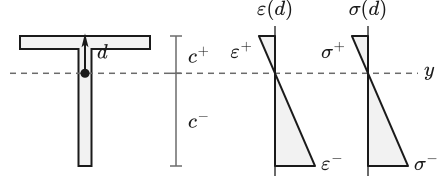
The derivation follows the Euler–Bernoulli model. The coordinate measures the signed distance from the stress-free neutral axis in the direction of the normal ; the case shown is that points in the positive direction. Plane cross-sections remain plane. The longitudinal strain therefore varies linearly with and with the curvature .1
In the linear-elastic material, the stress is proportional to the strain. It is therefore also linearly distributed.1
Without an external axial force, the resultant axial force is zero: tensile and compressive stresses must cancel over the cross-section. For a homogeneous cross-section, it follows that the neutral axis coincides with the centroidal axis.1 At the same time, the moment of the stresses must correspond to the bending moment. This yields the well-known relation , and with it can be eliminated from equation 2.1
For a given bending moment, equation 3 does not contain Young’s modulus: the elastic bending stress then depends only on the moment and the cross-section geometry.1 The material enters elsewhere: governs deformation, while the strength value provides the reference for the assessment. The sign follows the SpanDraft convention: for a positive, sagging moment, the side with positive is in compression.
Extreme fibers and section moduli
Because the distribution is linear, the stress magnitude grows with the distance from the centroidal axis. It is largest at the extreme fibers, that is, where the cross-section reaches its greatest distance on each side of the axis. This can be a single point or an entire edge. The distances and and the two section moduli of the selected bending axis are determined in the chapter Cross-section geometry and properties.
Inserting the edge distances into equation 3 yields the two extreme fiber stresses with their sign:
and thus belong to the geometric sides of the cross-section. They do not stand for tension and compression.
The governing extreme fiber
If the edge distances are equal on both sides of the bending axis, for example for a cross-section symmetric about this axis, holds. If they differ, as for the T-section about the axis , the extreme fiber that is farther away carries the larger stress magnitude. Since both section moduli contain the same , the smaller belongs to it. This holds independently of the sign of the moment: a change of sign swaps tension and compression but not the magnitudes (Figure 2).
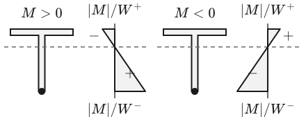
SpanDraft therefore determines the maximum elastic bending stress, the largest stress magnitude in the beam, directly with the smaller of the two section moduli:
Analytical
Beam theory provides a stress with sign for every location and every extreme fiber. Tension and compression can thus be stated separately.
SpanDraft
SpanDraft reports exactly one non-negative value: the largest stress magnitude in the beam. The result contains no assignment to tension or compression or to a specific side of the section. The orientation of the section in the bending plane is not part of the model.
For manually defined cross-sections, only one section modulus is entered per axis. SpanDraft then sets , and equation 6 becomes . This is a model assumption and not a property derived from the geometry. The one bending axis that is selected for the beam model is always used.
The governing location
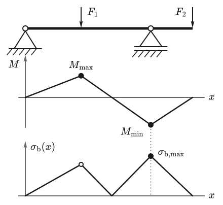
Material and cross-section are constant over the beam length. The extreme fiber stresses are therefore everywhere proportional to the moment, and the largest stress magnitude lies where the largest moment magnitude lies. SpanDraft needs no search of its own for this. The solver already knows the largest and the smallest bending moment as analytical extreme values, and the evaluation selects the one with the larger magnitude from them.
There is thus neither a second calculation nor additional evaluation locations or values from the diagram. Value and location come unchanged from the selected extreme value of the solver, including the side at a jump location. “Left” and “right” denote the side along the beam axis and not the upper or lower extreme fiber.
Figure 3 shows this for a beam with an overhang: the support moment with the larger magnitude determines the maximum bending stress, the smaller span moment remains below it.
Deep dive: equal moment magnitudes
In symmetric systems, the magnitudes of the largest and the smallest moment can coincide numerically. To keep rounding residues from deciding the selection by chance, two magnitudes count as equal if they differ relatively by at most 64 , with the machine epsilon of about . This is no technical tolerance and no absolute threshold in SI units.
In such a tie, the smaller position counts and then the left side before the right. If these are also equal, the smallest moment remains selected. The stress practically does not depend on this choice, but the reported location does. In the unloaded case, moment and stress are exactly zero.
Example: T-section
The example is the single-span beam from the chapter Stations and equation system: , point force at 1.2 m. The span moment is . Because the system is statically determinate, this value holds independently of the cross-section. New here is a T-section without fillet, with the flange on top, and the material S235JR.
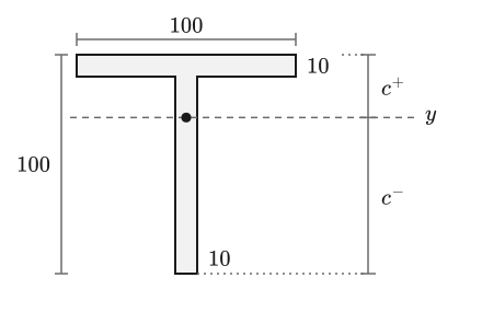
The table compares the hand calculation with the result of a SpanDraft calculation run. The centroid lies 71.3158 mm above the bottom edge, thus close to the flange. The lower extreme fiber is therefore governing.
| Quantity | Analytical | SpanDraft |
|---|---|---|
| in mm² | 1900 | 1900 |
| in | 1.80004 | 1.80004 |
| in | 62.7538 | 62.7538 |
| in | 25.2405 | 25.2405 |
| in Nm | 1092 | 1092 |
| in MPa | 43.2639 | 43.2639 |
is the smaller section modulus here and thus governing. If the direction of the force is reversed, the moment changes its sign, but remains the same at 43.2639 MPa. The value would also remain the same for a section rotated by 180°: and swap roles, the smaller one remains the same.
When tension and compression are to be assessed separately
The largest stress magnitude and the largest tensile stress can lie at different locations. This is shown by the beam from Figure 3 with the same T-section. It is 6 m long and rests at 0 and 4.5 m. At 2 m, 1000 N act downward, and at the end of the overhang 600 N. A hand calculation with equation 5 yields the following extreme fiber stresses at the two moment extrema; tension is positive.
| Location | in Nm | Top in MPa | Bottom in MPa |
|---|---|---|---|
| 711.11 | −11.33 | +28.17 | |
| −900 | +14.34 | −35.66 |
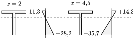
For this system, SpanDraft reports at . This is the largest stress magnitude; according to the hand calculation, this fiber is in compression there. The largest tensile stress is 28.17 MPa and lies 2.5 m away.
For the comparison with a single strength value that applies equally to tension and compression, the magnitude is the appropriate quantity. If tension and compression are to be assessed separately, the elastic extreme fiber stresses can be determined as above from the moment curve and from and , provided the orientation of the section in the bending plane is known. For brittle materials, adhesive bonds or the buckling of compressed thin sheets, this alone is not sufficient: separate failure criteria and verifications are required there.
What this value covers
is the elastic normal stress from the bending moment about the selected axis. Shear stresses, local stress peaks and superpositions with other stresses are not contained in it. The classification and the specific limits are described in the chapter Safety factor and assessment limits. How the values appear in the application is shown in the help under Bending stress and safety factor.
Sources
- David Roylance. Stresses in Beams. Mechanics of Materials, Massachusetts Institute of Technology / MIT OpenCourseWare. 2000. Accessed .