 SpanDraft
Parametric cross-section shapes
From parameters to contour
Inputs are exclusively geometric dimensions such as width, height, wall thickness, diameter or radius. These dimensions define a closed contour in the local plane, whose bounding box begins at the bottom left at and . Area, centroid and all further properties are then calculated from this contour as described in the chapter Cross-section geometry and properties.
Orthogonal sections are built by the same construction logic. SpanDraft starts with the sharp-edged base contour. At a corner with radius , the two adjoining straight lines are set back by , and a tangential circular arc replaces the corner.
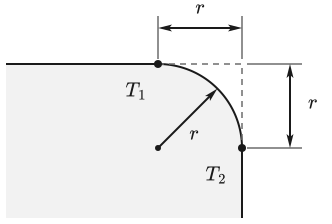
If an edge of length carries the radii and at its two ends, the straight line that remains of it is
The remaining length decides the contour:
- : The straight line is retained between the arcs.
- : The arcs meet at a common tangent point, the straight line is omitted.
- : The radii overlap, the input is invalid.
A radius means a sharp corner.
Simple solid sections as reference cases
Rectangle and circle have known closed-form solutions. SpanDraft uses no special algorithms of its own for them, so they serve as check cases of the general contour evaluation.
Rectangle
The contour of the rectangle consists of four straight lines around the region
The general contour evaluation must yield the known values1:
Circle
The circle with diameter has radius and center . Its contour consists of exact circular arcs and follows the same contour path. The reference values are1:
Hollow sections
Hollow sections consist of an outer contour and an inner contour. The evaluation subtracts the contributions of the inner contour from those of the outer contour: outer contour minus inner contour.
Rectangular hollow section
The rectangular hollow section is described by the outer dimensions and , the constant wall thickness and the outer radius . The inner contour follows from them:
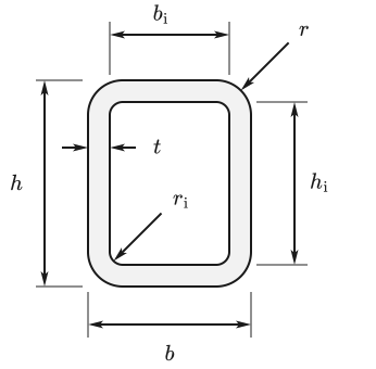
The radius defines three cases:
- : Outer and inner contour are sharp-edged.
- : The outer contour is rounded, the inner contour remains sharp-edged.
- : Both contours are rounded.
The inner contour must have positive dimensions, and the outer radii must not overlap. This requires and .
For the check case , the following holds
With a fillet, SpanDraft evaluates the complete arc contours, not a simplified rectangle formula.
Circular hollow section
The circular hollow section is described by the outer diameter and the wall thickness . Outer and inner circle are concentric:
For an inner circle to exist, must hold. The reference values are1:
Sections made of web and flange
I/H, U and T sections use the same parameters: height , width , web thickness , flange thickness and radius . Their contour is an orthogonal base polygon whose concave web–flange transitions are then rounded. The outer corners remain sharp.
| Shape | Construction | Radius condition |
|---|---|---|
| I/H | centered web, two equal flanges, four transitions | |
| U | web on the left, two flanges to the right, two transitions | |
| T | centered web, flange on top, two transitions |
In addition, and apply to the I/H and U sections, and and to the T section.
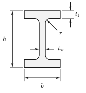
The mechanical differences between the three shapes follow from their geometry:
- The I/H section is doubly symmetric. The centroid lies in the middle, and both sides of each axis have the same extreme fiber distance.
- The U section is symmetric about the horizontal center line. Its centroid is shifted horizontally toward the web, yet holds. For the axis , the two extreme fiber distances differ.
- The T section is symmetric about the vertical center line. Its centroid does not in general lie at , so and can differ.
These properties arise from the contour and are not separately stored special properties.
Angle section and principal axes
The angle section starts from a sharp-edged base polygon with the dimensions , and the common leg thickness :
Only the inner corner receives the radius . The geometry is valid if and hold.
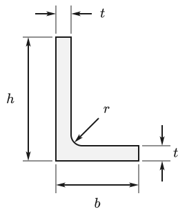
The normal general evaluation follows: → centroid → , , → , . The technical bending axes are then the principal axes:
The seven other shapes offer and ; the position and angle of the principal axes are shown in the chapter Cross-section geometry and properties.
The equal-leg angle is not a special algorithm of its own. For , the same calculation yields and thus a principal axis angle of 45° on the diagonal axis of symmetry.
Symmetry is a result of the geometry
SpanDraft does not use symmetry as a special calculation. Rectangle, circle and I/H section are also evaluated via their general contour. The following properties therefore emerge from the geometry rather than being assumed:
- the centroid lies in the middle,
- holds,
- holds for the circle.
Input limits and geometric validity
The conditions of the individual shapes ensure the same geometric properties:
- positive inner dimensions for hollow sections
- positive web and flange remainders for open sections
- no overlapping fillets
- no degenerate contour
SpanDraft rejects invalid inputs. They are not repaired automatically by reducing the radius, clipping or shifted contour points.
Manual cross-sections
Manual cross-sections follow a different path: they bypass the sequence parameters → contour → integration. The area and the values and for one or two axes are entered directly.
Without geometry, the centroid, , the principal axis angle and different extreme fiber distances cannot be reconstructed. Because only one section modulus is available per axis,
therefore holds.
Model limits of the parametric shapes
The shapes deliberately represent only a limited parametrization:
- rectangular hollow section: constant wall thickness
- I/H and U section: equal upper and lower flange thickness
- web–flange sections: one common inner radius
- angle section: equal leg thickness
- no parametrized outer radii for I/H, U, T and angle sections
- no freely composable contour
The simple analytical cases in this chapter serve as reference cases in the regular product tests. The Solver verification does not cover the cross-section properties.
Sources
- Dietmar Gross; Werner Hauger; Jörg Schröder; Wolfgang A. Wall. Technische Mechanik 2 — Elastostatik. 15th edition. Springer Vieweg, Berlin, Heidelberg. 2024. DOI 10.1007/978-3-662-68423-8. Accessed .