 SpanDraft
Stations and equation system
Event stations and mechanical stations
The chapter State variables and transfer transfers the state through a section in which only loads act. At supports, this no longer holds: a support holds the deflection fixed and develops an initially unknown reaction force for it. SpanDraft therefore distinguishes two kinds of locations on the beam axis:
- Event stations are all locations at which a result can change: beam ends, supports, point forces, point moments and the boundaries of every distributed load, also for loads of magnitude zero. They divide the beam into pieces in which every curve is a single polynomial, and are the locations at which SpanDraft outputs nodal results.
- Mechanical stations are only the beam ends and the supports. Unknowns arise only there. The region between two consecutive mechanical stations is called a section.
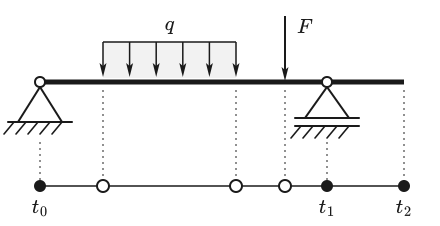
Positions are compared exactly. Two loads or supports form a common station if and only if their stored positions are equal. Close but different values remain separate, even if they differ only by the smallest representable difference. There is no rounding to neighboring locations and no minimum distance.
Rules at the stations
At every mechanical station, a left-hand and a right-hand state meet. The left-hand one is the transfer through the section before it. For each of the four components, the station fixes exactly one rule: the component is either prescribed, it passes continuously or with a known load jump, or its jump is free because an unknown reaction acts there.
| Station | ||||
|---|---|---|---|---|
| Roller support, pinned support | continuous | jump | jump free | |
| Fixed support | jump free | jump free | ||
| Free beam end | continuous | continuous | jump | jump |
Outside the beam, there is no moment and no shear force. At the left end, the left-hand state is therefore , and at the right end, the right-hand state must satisfy . and are the point force and point moment exactly at the station; loads directly on a support are included there as a jump. If different support types are at the same position, their constraints combine: pinned support and fixed support together act like a fixed support.
The equation system arises from the rules:
- Unknowns are the components of the right-hand state that are neither prescribed nor determined from known values.
- Equations are the rules “continuous” and “known jump”, whose left-hand side comes from the transfer.
- Prescribed values such as at the support are exactly zero. They are not kept as an equation but substituted before solving.
- Free jumps yield no equation. They belong to a support reaction that is determined after solving.
Each prescribed component removes one unknown, each free jump one equation. The number of equations therefore equals the number of unknowns. Load positions change nothing about this: an additional load changes only the right-hand side of the system, not its matrix.
Example: off-center point force
A beam with rests on a pinned support at the left and a roller support at the right. It carries a point force at . With and , . The force location divides the single section into two pieces but creates no unknown.
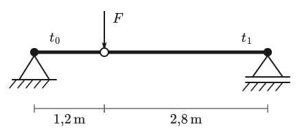
At the left station , on the left. The pinned support prescribes , passes continuously without a point moment, so . The rotation and the shear force to the right of the station remain unknown; its jump represents the support reaction. At the right station , , and are prescribed; only is unknown. With and the load integrals of the point force, the three rules at yield three equations:
Arranged by the unknowns, this is a linear system with three rows:
The last row gives , the first then and the second . The deflection under the force follows from the transfer up to the location : .
For checking, the closed-form solutions of beam theory serve, which result with by section-by-section integration.1
| Quantity | Analytical | SpanDraft |
|---|---|---|
| in N | 910.000 | 910.000 |
| in N | 390.000 | 390.000 |
| in mm | −0.728000 | −0.728000 |
| in mrad | −0.736667 | −0.736667 |
| in mrad | −0.346667 | −0.346667 |
| in mrad | 0.563333 | 0.563333 |
The table rounds to six significant digits. With the full number of digits, the two columns differ only by relative amounts of the order of , that is, by the rounding of floating-point arithmetic. Equilibrium also holds: .
Several spans
With several supports, the same pattern repeats. Each equation at a station uses only unknowns of this station and the preceding one, because the transfer extends only through one section. Figure 3 shows this for a continuous beam on three supports: the nonzero entries lie in a narrow band. At the interior support , , and to the right of the station are unknown; the jump of represents the support reaction.
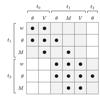
The size of the system grows with the number of supports, not with the number of loads. A single-span beam with any number of loads always leads to three unknowns.
Analytical
The common direct stiffness method sets up equilibrium at nodes. Nodes arise at supports and usually also at loads, and element stiffnesses such as act between them.2 A very short element next to a long one produces entries of very different magnitude, whose sum contains the actual information.
SpanDraft
The state formulation couples neighboring stations through the transfer. A short section means a transfer close to the identity matrix, not a large stiffness. Loads change only the right-hand side. For the same model, both methods deliver the same mechanical solution.
When there is no solution
A connected beam can move in the plane as a rigid body without deforming: axially as and in the bending plane as a straight line with constant rotation . As long as one of these motions is possible, no internal forces arise, and the problem has no unique solution.
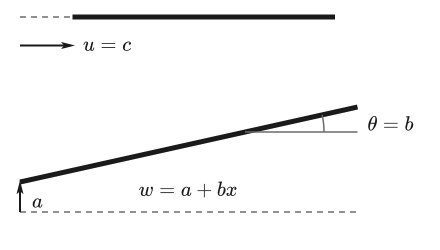
This gives the stability condition: the model needs at least one constraint on and, in addition, either a fixed support or constraints on at two different positions. SpanDraft checks this before setting up the equation system, independently of loads and stiffness, and also for unloaded models. The check works exactly with the stored positions and needs no tolerance: two supports at a very small distance prevent tilting, two supports at the same position do not.
A beam on two roller supports is therefore rejected, even though all loads act transversely: its axial position would be undetermined. SpanDraft then reports “Insufficient support”. An unstable support arrangement is thereby distinguished from a numerical problem, which the chapter Numerical solution and accuracy covers.
The practical checking steps for missing results are given in the help under Troubleshooting.
Support reactions
After solving, all states are known. A support reaction is the part of the jump that the loads at the station do not explain:
This is the jump condition from the chapter Loads, supports and internal forces and moments, solved for the reaction. In the example, and on the left, so . On the right, jumps from −390 N to zero, so .
Loads directly on a support show the advantage of this form. A force of −1250 N exactly above the interior support of a continuous beam causes no deformation: all states remain zero, and the jump yields .
Reactions are output only for constrained directions, once per station and direction. If several supports are at the same position, their common reaction is not divided, because a division would not be unique there. A reaction of exactly zero in a constrained direction is a valid result; in free directions there is no reaction. Since SpanDraft offers no external axial loads, the axial reaction at a pinned support and a fixed support is always exactly zero.
Limits of the method
The method calculates exactly one straight beam along the axis. The method has the following limitations:
- Frames and spatial structures are not supported.
- Supports are rigid. Prescribed support movements, elastic supports and internal hinges are not supported.
- The longitudinal direction is checked only for its rigid-body motion; a loaded axial system is not solved.
- The method provides no buckling or other stability verification. “Stability” in this chapter only means that the beam is not freely movable.
How the complete curves and extreme values arise from the solved states is described in the chapter Continuous results and extreme values.
Sources
- Dietmar Gross; Werner Hauger; Jörg Schröder; Wolfgang A. Wall. Technische Mechanik 2 — Elastostatik. 15th edition. Springer Vieweg, Berlin, Heidelberg. 2024. DOI 10.1007/978-3-662-68423-8. Accessed .
- Carlos A. Felippa. The Direct Stiffness Method I. Introduction to Finite Element Methods, Chapter 2, University of Colorado Boulder. Accessed .